
Engineering and fabrication industries continue to advance, thanks to rapid improvements in design and manufacturing technology. At the centre of this progress are CAD (Computer-Aided Design) and CAM (Computer-Aided Manufacturing)—two systems that bridge the gap between concepts and physical production.
These tools are not just digital drawing aids or automated machine controls. They shape the entire lifecycle of engineering work, from concept generation and design validation to part programming and final fabrication. Their importance becomes particularly clear in specialised areas like prototyping, machining, and fabrication of complex assemblies.
Whether you’re working on mechanical enclosures, components, or architectural metalwork, the combination of CAD & CAM ensures projects stay accurate, efficient, and within budget.
For those wanting to understand design-to-manufacture workflows, it’s also useful to study guides that cover all about sheet metal, as this is one of the most common applications for these technologies.
Understanding the Basics of CAD & CAM
What CAD Does in Engineering
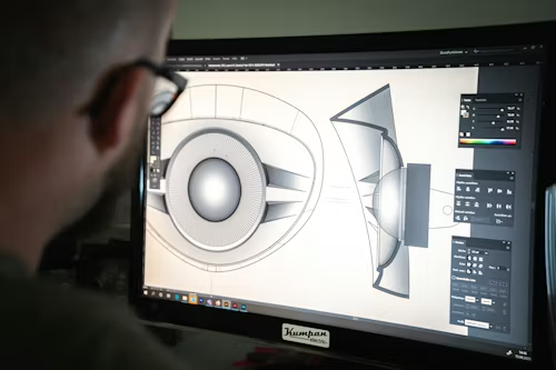
CAD software is used to design parts, products, or systems in 2D or 3D. Engineers use it to create accurate models with defined geometry, dimensions, and tolerances. These designs form the foundation for simulation, analysis, and prototyping.
CAD is also used to test structural integrity, heat flow, and movement through digital simulations. This saves time and materials during physical prototyping and allows early design corrections before anything is manufactured.
What CAM Does in Fabrication
CAM software translates CAD designs into instructions that machines can understand. These instructions—usually in G-code format—control CNC mills, lathes, routers, laser cutters, and waterjet systems.
CAM selects cutting paths, speeds, and tool changes to optimise production. The software ensures that parts are made accurately, consistently, and with minimal waste, especially when complex shapes or tight tolerances are involved.
Design Efficiency Through CAD
Reduced Errors and Design Rework
Using CAD reduces drawing errors that commonly occur in manual drafting. Dimensioning, tolerancing, and relationships between components are handled with automated rules. This minimises mistakes during assembly or fabrication.
Designers can also make updates easily. Changing one feature in a 3D model automatically adjusts dependent elements. This saves hours compared to redrawing entire parts or assemblies.
Better Communication Across Teams
Design files can be shared electronically, making it easier for teams in different locations to collaborate. Engineers, machinists, and fabricators can all work from the same model, reducing confusion and rework.
CAD files also integrate well with product lifecycle management (PLM) systems, allowing version control and traceability of changes.
Enhancing Fabrication Accuracy with CAM
High Precision in Machining
CAM software provides the precision required for modern fabrication. It creates machine instructions that reflect the exact dimensions from the CAD model, leaving little room for manual error.
Tolerances are easier to maintain, especially when repeatability is essential. This is particularly valuable in batch production, where every part must match the last.
Time-Saving Toolpath Optimisation
Toolpaths—the routes machines take when cutting—are optimised for both speed and accuracy in CAM. By calculating the shortest and most efficient cutting patterns, the software reduces material waste and wear on tools.
These optimisations are difficult to achieve manually and would take hours of programming time without CAM software.
CAD & CAM in Sheet Metal Design and Fabrication
Flat Patterns and Bend Allowances
One of the most common applications of CAD & CAM is in sheet metal work. CAD tools help engineers unfold 3D parts into flat patterns while accounting for bend allowances and material thickness.
The software automatically adjusts dimensions based on material properties, ensuring the final bent part meets design specifications. This is essential for brackets, housings, enclosures, and chassis.
Nesting and Material Usage
CAM software assists with nesting, which is the arrangement of multiple flat parts on a sheet to minimise material waste. Efficient nesting can drastically reduce scrap, especially when expensive metals like stainless steel or aluminium are used.
Integration with CNC Machining
Faster Setup Times
With CAM, once the program is created, setup on the CNC machine is faster and more accurate. The program includes all tool paths, spindle speeds, and feed rates. Operators simply load the program and follow prompts for tooling and fixturing.
This minimises downtime and increases productivity, especially in shops that run multiple short production cycles.
Consistency Across Batches
Repeatability is another benefit. Once a CAM program is proven, it can be reused without changes, ensuring that every part made is consistent with the original specification. This is particularly useful for industries with strict quality controls.
Supporting Advanced Manufacturing Techniques
5-Axis Machining and Complex Geometry
CAD & CAM systems are essential for 5-axis machining, which allows tools to move along five different axes simultaneously. This enables the fabrication of complex parts that would otherwise require multiple setups.
Industries such as aerospace and medical engineering rely on this capability for components with curved surfaces, compound angles, or intricate details.
Additive Manufacturing Integration
CAD & CAM aren’t just for subtractive processes like milling and turning. They also play a role in additive manufacturing (3D printing). CAD provides the model, and CAM can help generate tool paths for hybrid machines that combine printing and milling in one setup.
Reducing Production Costs with Digital Workflow
Fewer Physical Prototypes
By simulating the performance of a design within CAD, fewer physical prototypes are needed. This leads to savings in time, materials, and labour. Engineers can validate and optimise the model digitally before it goes to production.
Efficient Job Planning
CAM helps plan tool changes, machining order, and cycle times. It can simulate the entire manufacturing process, allowing planners to identify bottlenecks or inefficiencies before the job hits the shop floor.
Supporting Industry Standards and Compliance
Better Traceability
Engineering industries require compliance with local and international standards. CAD & CAM software often includes features to track revision history, apply material certifications, and manage documentation.
These systems are particularly useful in industries like defence, transport, and construction, where every detail must be documented for approval.
Reduced Inspection Failures
Because the parts are made exactly to the CAD model, fewer failures occur during inspection. CAM-generated paths produce consistent results, reducing the chance of non-conforming parts leaving the shop.
Frequently Asked Questions
Can CAD & CAM be used for both large and small production runs?
Yes. CAD & CAM are effective for both one-off prototypes and large production batches. For small runs, they offer speed and accuracy. For larger volumes, they provide consistency and repeatability across parts.
Is it difficult to learn CAD & CAM software?
Learning the basics is straightforward with training. Many platforms offer user-friendly interfaces and online resources. However, mastering advanced features like multi-axis machining or simulation requires practice and experience.
Do CAD & CAM systems work with all materials?
Most systems are material-agnostic. As long as the properties are known—such as hardness or thickness—the software can generate tool paths for metals, plastics, and composites. Special tooling may be needed for harder materials.
Conclusion
The role of CAD & CAM in modern engineering and fabrication is more than convenience—it’s foundational. These tools enable faster, more accurate, and more consistent results across all stages of design and manufacturing. From reducing errors in drawing to generating precise instructions for machining, they transform how parts are developed, validated, and produced.
When integrated effectively, CAD & CAM lead to reduced waste, better use of materials, and smoother project timelines. Whether you’re designing structural steel frames, intricate components, or looking to learn all about sheet metal, understanding how these systems interact is essential.
As the manufacturing industry moves toward higher efficiency and digital workflows, the use of CAD & CAM will only become more widespread. Investing in these tools—along with proper training—can give engineers and fabricators a strong advantage in meeting today’s project demands.